Packet Tracer – Troubleshooting Single-Area OSPFv2
https://drive.google.com/open?id=1qeV2etrNpQtGyld5gGL4Yw5SxPAgXVgr
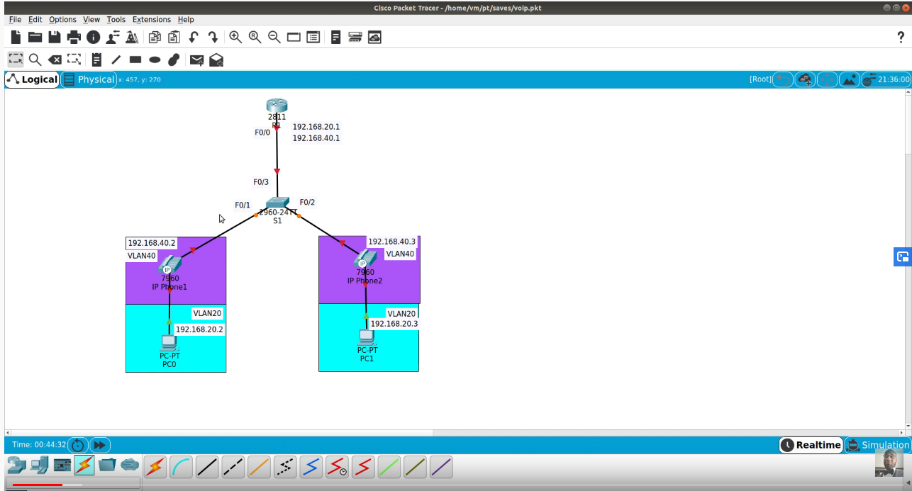
Topology
Scenario In this activity, you will troubleshoot OSPF routing issues using ping and show commands to identify errors in the network configuration. Then, you will document the errors you discover and implement an appropriate solution. Finally, you will verify end-to-end connectivity is restored.
Packet Tracer – Troubleshooting Single-Area OSPFv2
Troubleshooting Process 1. Use testing commands to discover connectivity problems in the network and document the problem in the Documentation Table. 2. Use verification commands to discover the source of the problem and devise an appropriate solution to implement. Document the proposed solution in the Documentation Table. 3. Implement each solution one at a time and verify if the problem is resolved. Indicate the resolution status in the Documentation Table. 4. If the problem is not resolved, it may be necessary to first remove the implemented solution before returning to Step 2. 5. Once all identified problems are resolved, test for end-to-end connectivity.
Documentation Table
Device Identified Problem Proposed Solution Resolved.
OSPF
Open Shortest Path First (OSPF) was designed as an interior gateway protocol, for use in an autonomous system such as a local area network (LAN). It implements Dijkstra’s algorithm, also known as the shortest path first (SPF) algorithm. As a link-state routing protocol it was based on the link-state algorithm developed for the ARPANET in 1980 and the IS-IS routing protocol. OSPF was first standardised in 1989 as RFC 1131, which is now known as OSPF version 1. The development work for OSPF prior to its codification as open standard was undertaken largely by the Digital Equipment Corporation, which developed its own proprietary DECnet protocols.
Routing protocols like OSPF calculate the shortest route to a destination through the network based on an algorithm. The first routing protocol that was widely implemented, the Routing Information Protocol (RIP), calculated the shortest route based on hops, that is the number of routers that an IP packet had to traverse to reach the destination host. RIP successfully implemented dynamic routing, where routing tables change if the network topology changes. But RIP did not adapt its routing according to changing network conditions, such as data-transfer rate. Demand grew for a dynamic routing protocol that could calculate the fastest route to a destination. OSPF was developed so that the shortest path through a network was calculated based on the cost of the route, taking into account bandwidth, delay and load.[4] Therefore OSPF undertakes route cost calculation on the basis of link-cost parameters, which can be weighted by the administrator. OSPF was quickly adopted because it became known for reliably calculating routes through large and complex local area networks.
As a link state routing protocol
As a link state routing protocol, OSPF maintains link state databases, which are really network topology maps, on every router on which it is implemented. The state of a given route in the network is the cost, and OSPF algorithm allows every router to calculate the cost of the routes to any given reachable destination. Unless the administrator has made a configuration, the link cost of a path connected to a router is determined by the bit rate (1 Gbit/s, 10 Gbit/s, etc) of the interface. A router interface with OSPF will then advertise its link cost to neighbouring routers through multicast, known as the hello procedure. All routers with OSPF implementation keep sending hello packets, and thus changes in the cost of their links become known to neighbouring routers. The information about the cost of a link, that is the speed of a point to point connection between two routers, is then cascaded through the network because OSPF routers advertise the information they receive from one neighbouring router to all other neighbouring routers. This process of flooding link state information through the network is known as synchronisation. Based on this information, all routers with OSPF implementation continuously update their link state databases with information about the network topology and adjust their routing tables.
An OSPF network can be structured, or subdivided, into routing areas to simplify administration and optimize traffic and resource utilization. Areas are identified by 32-bit numbers, expressed either simply in decimal, or often in the same dot-decimal notation used for IPv4 addresses. By convention, area 0 (zero), or 0.0.0.0, represents the core or backbone area of an OSPF network. While the identifications of other areas may be chosen at will; administrators often select the IP address of a main router in an area as the area identifier. Each additional area must have a connection to the OSPF backbone area. Such connections are maintained by an interconnecting router, known as an area border router (ABR). An ABR maintains separate link-state databases for each area it serves and maintains summarized routes for all areas in the network.