Introduction to inter-vlan routing
When we learnt about VLANs, we said that each VLAN is usually on its own subnet, switches mainly operate at layer 2 of the OSI model and therefore they do not examine the logical addresses. Therefore, user nodes located on different VLANs cannot communicate by default. In many cases, we may need connectivity between users located on different VLANs. The way this can be accomplished is through inter-VLAN routing.
In this course, we will look at one type of inter-VLAN routing, which is through the use of a router.
Definition
Inter-VLAN routing can be defined as a way to forward traffic between different VLAN by implementing a router in the network. As we learnt previously, VLANs logically segment the switch into different subnets, when a router is connected to the switch, an administrator can configure the router to forward the traffic between the various VLANs configured on the switch. The user nodes in the VLANs forwards traffic to the router which then forwards the traffic to the destination network regardless of the VLAN configured on the switch.
Information destined for PC B, leaves PC A with the VLAN 20 tag, when it gets to R1, the router, changes the format of this message from VLAN 20, to VLAN 30, it then sends it back to the switch and the switch finally sends the message to its intended recipient PC B.
There are two ways in which inter-VLAN routing can be accomplished.
- Traditional inter-VLAN routing
- Router-on-a-stick
Traditional inter-VLAN routing
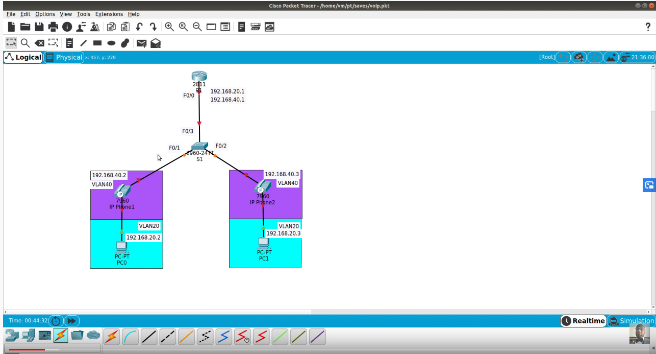
In this type of inter-VLAN routing, a router is usually connected to the switch using multiple interfaces. One for each VLAN. The interfaces on the router are configured as the default gateways for the VLANs configured on the switch.
The ports that connect to the router from the switch are configured in access mode in their corresponding VLANs.
When a user node sends a message to a user connected to a different VLAN, the message moves from their node to the access port that connects to the router on their VLAN. When the router receives the packet, it examines the packet’s destination IP address and forwards it to the correct network using the access port for the destination VLAN. The switch now can forward the frame to the destination node since the router changed the VLAN information from the source VLAN to the destination VLAN.