ICND2 5.1.3.6 Configuring Router-on-a-Stick Inter-VLAN Routing
What is Router-on-a-Stick?
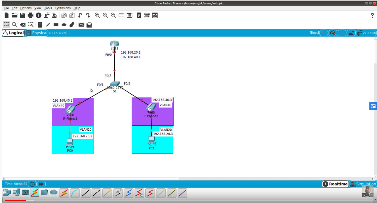
Router-on-a-stick is a term frequently used to describe a setup up that consists of a router and switch connected using one Ethernet link configured as an 802.1q trunk link. In this setup, the switch is configured with multiple VLANs and the router performs all routing between the different networks/VLANs.
While some believe the term ‘router-on-a-stick’ sounds a bit silly, it’s a very popular term and commonly used in networks where no layer-3 switch exists. A good example of a router-on-a-stick configuration (which also happens to be the one we are going to cover) would be a Call Manager Express installation where there is the need to split the VoIP network, consisting of your Cisco IP Phone devices, from your data network where all workstations and servers are located.
Packet Tracer – Configuring Router-on-a-Stick Inter-VLAN Routing
Addressing Table
| Device | Interface | IPv4 Address | Subnet Mask | Default Gateway |
| R1 | G0/0.10 | 172.17.10.1 | 255.255.255.0 | N/A |
| G0/0.30 | 172.17.30.1 | 255.255.255.0 | N/A | |
| PC1 | NIC | 172.17.10.10 | 255.255.255.0 | 172.17.10.1 |
| PC2 | NIC | 172.17.30.10 | 255.255.255.0 | 172.17.30.1 |
Objectives
Part 1: Test Connectivity without Inter-VLAN Routing
Part 2: Add VLANs to a Switch
Part 3: Configure Subinterfaces
Part 4: Test Connectivity with Inter-VLAN Routing
Scenario
In this activity, you will check for connectivity prior to implementing inter-VLAN routing. You will then configure VLANs and inter-VLAN routing. Finally, you will enable trunking and verify connectivity between VLANs.
Part 1: Test Connectivity Without Inter-VLAN Routing
Step 1: Ping between PC1 and PC3.
Wait for switch convergence or click Fast Forward Time a few times. When the link lights are green for PC1 and PC3, ping between PC1 and PC3. Because the two PCs are on separate networks and R1 is not configured, the ping fails.
Step 2: Switch to Simulation mode to monitor pings.
- Switch to Simulation mode by clicking the Simulationtab or pressing Shift+S.
- Click Capture/Forwardto see the steps the ping takes between PC1 and PC3. Notice how the ping never leaves PC1. What process failed and why?
Part 2: Add VLANs to a Switch
Step 1: Create VLANs on S1.
Return to Realtime mode and create VLAN 10 and VLAN 30 on S1.
Step 2: Assign VLANs to ports.
- Configure interface F0/6 and F0/11 as access ports and assign VLANs.
- Assign PC1to VLAN 10.
- Assign PC3to VLAN 30.
- Issue the show vlan briefcommand to verify VLAN configuration.
S1# show vlan brief
VLAN Name Status Ports
—- ——————————– ——— ——————————-
1 default active Fa0/1, Fa0/2, Fa0/3, Fa0/4
Fa0/5, Fa0/7, Fa0/8, Fa0/9
Fa0/10, Fa0/12, Fa0/13, Fa0/14
Fa0/15, Fa0/16, Fa0/17, Fa0/18
Fa0/19, Fa0/20, Fa0/21, Fa0/22
Fa0/23, Fa0/24, Gig1/1, Gig1/2
10 VLAN0010 active Fa0/11
30 VLAN0030 active Fa0/6
1002 fddi-default active
1003 token-ring-default active
1004 fddinet-default active
1005 trnet-default active
Step 3: Test connectivity between PC1 and PC3.
From PC1, ping PC3. The pings should still fail. Why were the pings unsuccessful?
Part 3: Configure Subinterfaces
Step 1: Configure subinterfaces on R1 using the 802.1Q encapsulation.
- Create the subinterface G0/0.10.
- Set the encapsulation type to 802.1Q and assign VLAN 10 to the subinterface.
- Refer to the Address Tableand assign the correct IP address to the subinterface.
- Repeat for the G0/0.30 subinterface.
Step 2: Verify Configuration.
- Use the show ip interface briefcommand to verify subinterface configuration. Both subinterfaces are down. Subinterfaces are virtual interfaces that are associated with a physical interface. Therefore, in order to enable subinterfaces, you must enable the physical interface that they are associated with.
- Enable the G0/0 interface. Verify that the subinterfaces are now active.
Part 4: Test Connectivity with Inter-VLAN Routing
Step 1: Ping between PC1 and PC3.
From PC1, ping PC3. The pings should still fail.
Step 2: Enable trunking.
- On S1,issue the show vlan command. What VLAN is G1/1 assigned to?
- Because the router was configured with multiple subinterfaces assigned to different VLANs, the switch port connecting to the router must be configured as a trunk. Enable trunking on interface G1/1.
- How can you determine that the interface is a trunk port using the show vlancommand?
- Issue the show interface trunkcommand to verify the interface is configured as a trunk.
Step 3: Switch to Simulation mode to monitor pings.
- Switch to Simulationmode by clicking the Simulation tab or pressing Shift+S.
- Click Capture/Forwardto see the steps the ping takes between PC1 and PC3.
- You should see ARP requests and replies between S1 and R1. Then ARP requests and replies between R1 and S3. Then PC1 can encapsulate an ICMP echo request with the proper data-link layer information and R1 will route the request to PC3.
Note: After the ARP process finishes, you may need to click Reset Simulation to see the ICMP process complete.
Suggested Scoring Rubric
Packet Tracer scores 60 points. The four questions are worth 10 points each.