Download Document and Packet Tracert File Here
Overview:
In the previous VTP lab we used Cisco Packet Tracer to demonstrate how to configure VLAN Trunking Protocol (VTP) in a server client environment. In this Packet Tracer activity we will learn about VTP transparent mode and how to configure it on a Cisco Catalyst switch.
VTP is a Cisco proprietary protocol that propagates the definition of Virtual Local Area Networks (VLAN) on the whole local area network. To do this, VTP carries VLAN information to all the switches in a VTP domain. VTP advertisements can be sent over ISL, 802.1q, IEEE 802.10 and LANE trunks. VTP is available on most of the Cisco Catalyst Family products.
VTP is a Cisco Layer 2 messaging protocol that manages the addition, deletion, and renaming of VLANs on a network-wide basis. VLAN and VTP reduce administration in a switched network. When you configure a new VLAN on one VTP server, the VLAN is distributed through all switches in the domain. This reduces the need to configure the same VLAN everywhere. VTP ensures that all switches in the VTP domain are aware of all VLANs.
VTP Transparent Mode:
There are occasions when you not want to isolate VLANs created on a switch to that switch alone. To answer this need Cisco has provided the transparent mode, VTP transparent switches do not participate in VTP. A VTP transparent switch does not advertise its VLAN configuration and does not synchronize its VLAN configuration based on received advertisements, but transparent switches do forward VTP advertisements that they receive out their trunk ports in VTP Version 2.
You might understand this how this works but still ask what would be the real world application of this VTP mode. Security would be the first thing that comes to my mind, consider the following:
One reason that I understand where one would configure a switch for transparent mode is for example the Accounting VLAN. Since that VLAN would only exist on that switch only and NOT propagated up to the VTP Server or down to the VTP Client switch, there shouldn’t be a way to use the network to “hack” into say, the Payroll computer by employees so that they can modify their pay-rate data so their paychecks will be bigger.
Another use would be in a test environment such as where you are just connecting switch into your production network for testing purpose only but you don’t want this switch to accidentally change your production network VLAN information.
Lab Objective:
The objective of this Free CCNA Lab Packet Tracer Activity is for you to learn and understand how to configure VTP Transparent Mode on Cisco Catalyst switches.
• Learn to create a VTP domain.
• Learn how to password protect the VTP domain.
• Learn to configure VTP mode command.
• Learn to configure Trunk lines between switches.
• Learn to create VLANs within the VTP domain
• Learn to assign ports to VLANs.
• Learn to use show commands to verify VTP operation.
Procedure:
1. Basic switch configuration.
- Hostnames.
- Passwords.
- Disable IP domain-lookup.
- Disable timeout.
2. Configure the VTP domain on all three switches as CCNA
3. Set the VTP domain password as cisco on all three switches.
4. Configure DSW-1 as a VTP Server switch.
5. Configure DSW-2 as VTP Transparent Mode
6. Configure ASW-1 and ASW-2 as a VTP Client switch.
7. Configure and verify an 802.1q trunk between Gig0/1 on DSW-1 and Gig0/1 of DSW-2.
8. Configure and verify an 802.1q trunk between Fa0/1 on DSW-2 and Fa0/24/1ASW-1.
9. Configure and verify an 802.1q trunk between Fa0/2 on DSW-2 and Fa0/24/ASW-2.
10. Configure and verify VLANs 10 and 20 on DSW-1 with the names provided in the table below.
11. Assign the VLANs to fa0/1 and fa0/2 of ASW-1 and ASW-2 as shown in the table below.
12. Configure and verify VLAN 100 on DSW-2 with the names provided in the table below.
13. Assign the VLANs to fa0/1 and fa0/2 of DSW-2 as shown in the table below
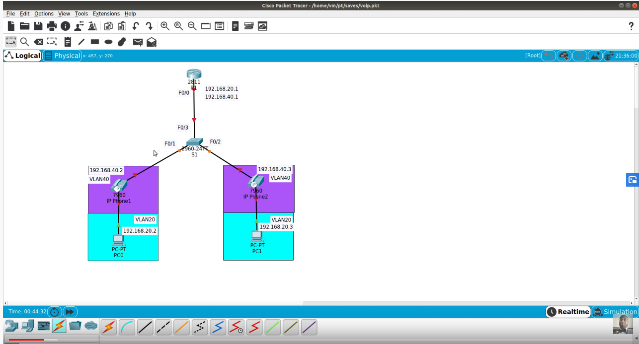
14. Assign IP address to PC-1, 2, 3, and 4 as shown in the network diagram.
15. Insure that VLAN 10, and 20 have propagated over DSW-1, ASW-1,2 but not on DSW-2
16. Insure the VLAN 100 is present onDSW-2 but not on DSW-1, ASW-1, and ASW-2
17. Test connectivity via your VLANs by pinging PC-4 from PC-1 and vice versa.
18. Test connectivity via your VLANs by pinging FS-1 from PC-1 and vice versa.
19. Test connectivity via your VLANs by pinging PC-5 from PC-2 and vice versa.
20. Test connectivity via your VLANs by pinging FS-2 from PC-3 and vice versa.